Product Features
Features
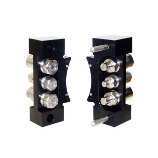
- Modular assembly that adapts commercial, high-pressure, no-drip, self-sealing fluid couplers to the ATI heavy Tool Changers.
- Designed to pass high-pressure fluids from the Master to the Tool for use by the customer’s tooling.
- Self-sealing valves to prevent leaks and drips.
- Supports multiple connections and equipped with pre-alignment pins to insure proper engagement of the couplers.
- The customer’s robot must overcome the pressure in the couplers when driving the Master and Tool modules together. The pump should be turned off during tool changes.
- The customer must use flexible lines for all plumbing connections. Hard pipe connections are not acceptable as they will not allow proper alignment and engagement of the coupler halves.
Materials
- Aluminum housings
- Steel bushings and pins
- Fluorocarbon seals
- Stainless steel couplers
| Specification | Value |
|---|---|
| Flow Rating |
0.46 for G 1/4 (at rated pressures) 1.23 for G 3/8 (at rated pressures) 2.26 for G 1/2 (at rated pressures) |
| Master Side Weight | |
| Tool Side Weight | |
| Operational Temperature Range | -28.9 °C to 65.6 °C |
| Utility Type | Hydraulic |
- Filter by Type
- Drawings
- Manuals
| Download | Download Type | Language |
|---|---|---|
| 9121-HC2-T | Drawings | English |
| 9121-HC4-T | Drawings | English |
| 9630-20-COUPLER | Drawings | English |
| 9630-20-HB2 | Drawings | English |
| 9630-20-HB6 | Drawings | English |
| 9630-20-HB8ZF2T1 | Drawings | English |
| 9630-20-HB9 | Drawings | English |
| 9630-20-HB9ZF2T1 | Drawings | English |
| 9630-20-HYD | Drawings | English |
| 9620-20-D-HBx | Manuals | English |
- Filter by Part Number
- 9121-HB2-M
- 9121-HB2-T
- 9121-HB6-M
- 9121-HB6-T
- 9121-HB8ZF2T1-M
- 9121-HB8ZF2T1-T
- 9121-HB9-M
- 9121-HB9-T
- 9121-HB9ZF2T1-M
- 9121-HB9ZF2T1-T
- 9121-HC2-T
- 9121-HC4-T
| Part Number | Description | ||
|---|---|---|---|
 |
9121-HB2-M | Hydraulic Module, (2) 2300 PSI G3/8, (1) 2300 PSI G1/4, Master side |
|
|
|
9121-HB2-T | Hydraulic Module, (2) 2300 PSI G3/8, (1) 2300 PSI G1/4, Tool side |
|
|
|
9121-HB6-M | Hydraulic Module, (2) 7200 PSI G3/8, Master side |
|
|
|
9121-HB6-T | Hydraulic Module, (2) 7200 PSI G3/8, Tool side |
|
|
|
9121-HB8ZF2T1-M | Hydraulic Module, (1) 7200 PSI G 1/4, SS Hardware, TDC Plated Alignment Parts – Master side |
|
|
|
9121-HB8ZF2T1-T | Hydraulic Module, (1) 7200 PSI G 1/4, SS Hardware, TDC Plated Alignment Parts – Tool side |
|
|
|
9121-HB9-M | Hydraulic Module, (2) 7200 PSI G1/2, Master side |
|
|
|
9121-HB9-T | Hydraulic Module, (2) 7200 PSI G1/2, Tool side |
|
|
|
9121-HB9ZF2T1-M | Hydraulic Module, (2) 7200 PSI G1/2, SS Hardware, TDC Plated Alignment Parts, Master side |
|
|
|
9121-HB9ZF2T1-T | Hydraulic Module, (2) 7200 PSI G1/2, SS Hardware, TDC Plated Alignment Parts, Tool side |
|
|
|
9121-HC2-T | Protective Cover used with the HB2-M through HB8-M modules when a tool module is not installed – Tool side |
|
|
|
9121-HC4-T | Protective Cover used with HB9-M when HB9-T is not installed – Tool side |
|