
Product Features
Features
- Power circuits are electrically isolated both from each other and the Tool Changer.
- Power circuits are designed to be water-resistant, but they are not waterproof.
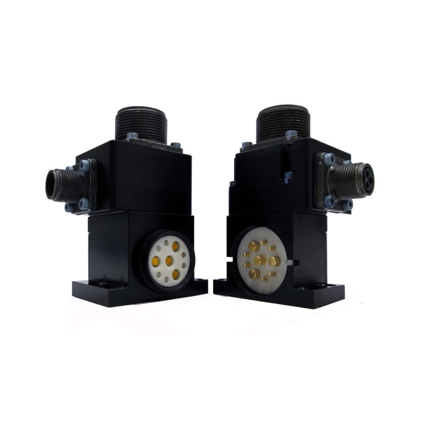
- Compliant spring probes are provided on the Master and fixed contact pins on the Tool.
- Master spring pins are recessed below an insulated surface on both the power circuits.
- DANGER! – For electrical modules using > 60 VDC or 42 VAC, NO contact should be attempted before removing power. This especially includes separation or insertion of the mating connectors or any contact with the Tool Changer or its components.
Materials
- Precious-metal-plated pins
- Amphenol connectors.
| Specification | Value |
|---|---|
| Electrical Rating |
13 Amp, 500VAC/700VDC (Pins 1, 4, 7, 10) 5 Amp/250VAC max (Pins 2, 3, 5, 6, 8, 9) |
| Master Side Weight | 0.29 kg |
| Tool Side Weight | 0.25 kg |
| Number of Total Pins | 7 |
| Pins Description |
Servo Power – 4 Servo Brake – 3 |
| Operational Temperature Range | -28.9 °C to 65.6 °C |
- Filter by Part Number
- 9120-REP7-M
- 9120-REP7-T
| Part Number | Description | ||
|---|---|---|---|
 |
9120-REP7-M | Servo Module with 4-pin MS Power, 3-pin MS Brake – Master side |
|
|
|
9120-REP7-T | Servo Module with 4-pin MS Power, 3-pin MS Brake – Tool side |
|